The Texas Instruments Launchpad and The MSP430G2231
A brief recording of my efforts and my findings with my first microprocessor.
Progress! Blinking Lights! | 12-Sept-2011
Finally! After reading up some on C++ and playing with other peoples work I've managed to create some code that causes the red and green LEDs to blink predictably. Importantly, I understand what each line of code does. Here you can see the code and a description for each line of it.
Even with this small amount of knowledge, it is possible to write useful applications for the device. You can see one great example here, where a LaunchPad and MSP430 are used to control a camera. I found this code extremely useful to get me where I am now as it is very well commented.
Even with this small amount of knowledge, it is possible to write useful applications for the device. You can see one great example here, where a LaunchPad and MSP430 are used to control a camera. I found this code extremely useful to get me where I am now as it is very well commented.
Learning C++ code | 11-Sept-2011
I've found a great, free pdf file to guide me through the basic concepts of C++ coding. You can view / download it here http://www.cplusplus.com/files/tutorial.pdf. I've read through the first 18 pages straight away and have learnt quite a bit. I now better understand some of my previously viewed code samples. It's late now so I'll probably read a lot more of the Ebook tomorrow and may even attempt to put some of my learnings into practise.
Looking at code | 7-Sept-2011
Last night I started looking at working code for the MSP430. The recommended coding software is Code Composer Studio and there are websites and videos that go into some detail on how to use it in general and to code the MSP430. After a few minutes reading it seems and is pretty straight forward to paste an existing project onto a blank source file and upload it (I'm sure that's technically correct although you'll read about downloading it) to the chip. My aim was to read through the basic code samples and adjust it slightly to do my bidding. While I did learn something, I also discovered that I will have to learn quite a bit about the C and C++ programming languages to make much use of this device. A challenge, no doubt, but also a great excuse to learn the language and put it to use. It won't happen anytime soon as I have other hobbies and interests as well as the fun responsibilities of being a Dad and full time worker, but, I hope it will happen.
Anyway, here's what I did manage to learn:
Like I say, I've had a play with the code with little success. I have ideas of how some of it works, but it's difficult to find something explaining the very basics online. I won't put any speculation on here until I am more confident about it being accurate. If you thing you can point me in the right direction, please, PLEASE, do get in touch!
Anyway, here's what I did manage to learn:
- Each set of completed code must start with #include<msp430g2231.h> (replace with your chip model followed by .h .
- The MSP430 chips have a Watchdog Timer. This timer runs by default and expects certain actions / code during the program. I believe it is to prevent errors, but, if not accounted for it will cause an error. If you're starting out, you can disable it in your projects and use it when you know how to or need to. To disable it, the following line of code is added at the top of the 'main' code: WDTCTL = WDTPW + WDTHOLD; .
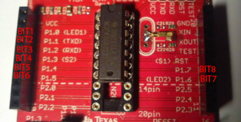
- By default, the MSP430G2231 has 8 usable digital pins. These pins can be used as inputs and outputs and have to defined as such in order to be used. They are marked on the board as pins 1.0 - 1.7 . Pin 1.0 is connected to LED1 which is red and pin 1.6 is connected to LED2 which is green. They are connected to the LEDs with a jumper which can be removed if you wish to use the pins on an external circuit. In code, the pins can be referred to by BITx. BIT1 is pin 1.0 and you can go up to BIT8 which is pin 1.7 (see the image on the left) .
Like I say, I've had a play with the code with little success. I have ideas of how some of it works, but it's difficult to find something explaining the very basics online. I won't put any speculation on here until I am more confident about it being accurate. If you thing you can point me in the right direction, please, PLEASE, do get in touch!
Starting out: The battery pack | 6-Sept-2011
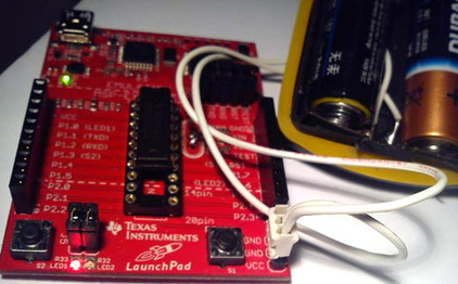
I've had my Launchpad for a while now and, since soldering the extras on to the board and trying a sample code to test it, I hadn't really done much. Well, a couple of days ago I figured it would make sanse to create a battery pack for the board (a nice easy place to start). I used the backing from an old bike light that holds two AA 1.5 Volt batteries, obviously capable of providing the 3 Volts required of the LaunchPad. To this I soldered two wires which were connected to a three pin header. The VCC (positive) pin is at one end and the GND (ground) is in two places, in the middle and at the other end. I've opted to use the center pin for ground so that no damage can be done to the board if the pack is connected the wrong way (it would just short the battery).
